Product Description
The spiral sand washing machine is 1 of the main equipments of ZheJiang HangZhou Mining Machinery Manufactory.
Over the past decades, with the continuous practice of domestic and foreign markets, the gradual upgrading of ancillary products, the current sand washing equipment has become a mature assembly line equipment of our factory.
Can handle material: It is suitable for washing, grading and cleaning of fine-grained and coarse-grained materials, and is mainly used in desliming and operation of large quantities of sand and CZPT used in construction sites, sand and CZPT factories, prefabrication plants, ore dressing plants and hydropower sites. (especially suitable for river sand, mountain sand, CZPT powder in CZPT yard and road-building mechanism sand).
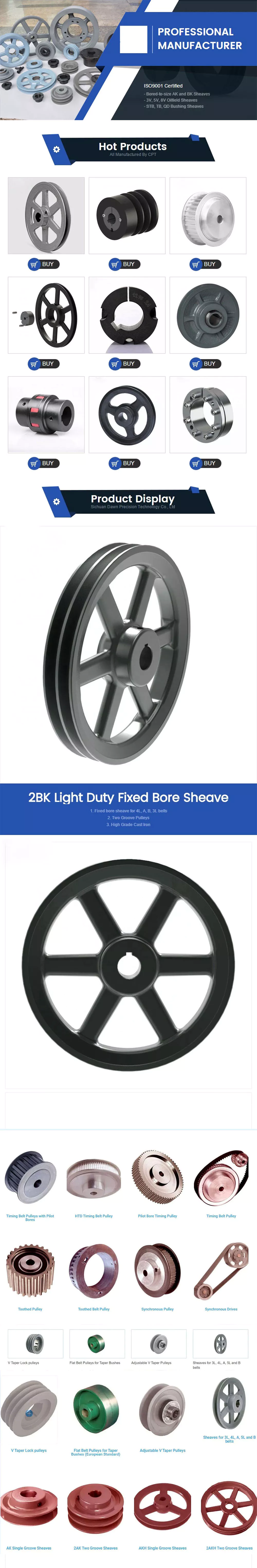
The sand washing machine is composed of gears, reducers, brackets, sedimentation tanks, impellers, pulleys, motors and other important parts.
- The transmission device:It is composed of the electric motor, big and small belt pulleys, triangle belt and gear reducer.
- Gear reducer: speed ratio i=68.61, a whole sealing oil bath type. The gear is steel cylinder helical gears. The materials of the gear reducer are HT20-40 with industrial pad liner(δ=0.5mm). The liner is smeared withfluid sealant. The reasonable design of the gear and the gear reducer ensures the accuracy of transmission.
- Screw arbor: Screw diameter D=920mm, Thread pitchS=445mm, HeadZ =1, Cylinder number N=15.5. The materials of screw blade is Q235A, δ=8mm armor plate jointed continuously to the hollow shaft. The screw of each thread pitch iscomposed of 6 liners. Liner materials are high manganese cast steel (ZGMn13). The screw liner is connected by bolt, nut and screw blade. Hollow shaft is seamless pipe (219X22) which ensures intensity and rigidity. On the both side, jointing ring flange which is connected to lug and under-part bearing respectively. This structure meets the demand of sand to wash, separate, and classify and dehydrate fully.
- Trough: It contains shell, input devices, right weir plates and left weir plates.Trough is steel plate jointed into water tight structure. Right and left weir plates and input devices are connected by bolt, nut, and grower washers. Right weir plate and left weir plate&=3(mm)rubber sheet for sealing.
On the bottom of trough, it installs sheet bending machine on 1 side which keeps a suitable clearance with the out edge of the impeller in order to move particles forward. Another side is gutter used for discharging moisture from sand. - Overflow platecan be adjusted: upgrade 1 or 2 weir plates, can curtail the valid length change the admission velocity of washing water, can increase working head and change overflow speed, getting rid of granule according to the demand of classification.
Wire plates can provide compensation when trough’s location tilts by the mistakes of assembling and installment.
Working principle: This sand washer should be installed with an angle of 15 degree,under the water tub, 3 weir plates form the sediment pool, the screw head is immersed in this pool, the screw is driven by electric motor through reducer rotating continuously, the fresh water is feeding from porous plate at bottom of sediment pool, this machine have 3 functions of washing, dewatering, classifying.
- Washing: The sand is feeding into the sediment pool from the feeding box, with the help of rotating screw blade, the sand is turning, rolling and grinding each other to eliminate impurity and water-air layer around sand to facilitate de-water. The fresh water rising current from the porous plate carries foreign matter to water surface and overflow the weir plate, to finish washing processing.
- De-watering: The sand with bigger density is sunken down to tub bottom, the screw blade push this sand upwards, when passing through upper tub of proper length above water level, the water is draining into sedimentpool from another drainage ditch, the de-watered sand is out from the discharging opening.
- Classifying: Material classifying is realized by overflowing the fine particle that does not meet the standard requirements. The controlling method is adjusting height of overflowing weir and adjusting speed of screw.
ZheJiang HangZhou Mining Machinery Manufactory consists of 3 branch factories.And it have 5 standard heavy industrial workshops covering 80,000 square meters,more than 160 machines used for gold processing,plug welding and assembling with large and medium sizes, and more than 500 works including over 50 administrators with intermediate and senior title and engineering technicians.
Pre-service: Enthusiasm
1)We will reply to your enquiry within 24 hours.
2)All your inquiries will be well explained by our experienced staff.
Services during the sales: Servant
1)Pre-check and accept products ahead of delivery
2)The purchase contract has a certain reputation guarantee, provide you the perfect product to your hands.
After-sale services: Faithfulness
1)Send technicians to customer’s local place for guiding the installation and adjustment, training operators.
2)In addition, our company provide 1 year warrantee to guarantee the machine runs consistently.
Three basic types of pulleys, their applications and ideal mechanical advantages
There are 3 basic types of pulleys: movable, fixed and compound. Each has its advantages and disadvantages, and you should be able to judge which type is best for your needs by looking at the table below. Once you have mastered the different types of pulleys, you can choose the right pulley for your next project. Now that you have mastered the 3 basic types, it is time to understand their applications and ideal mechanical advantages.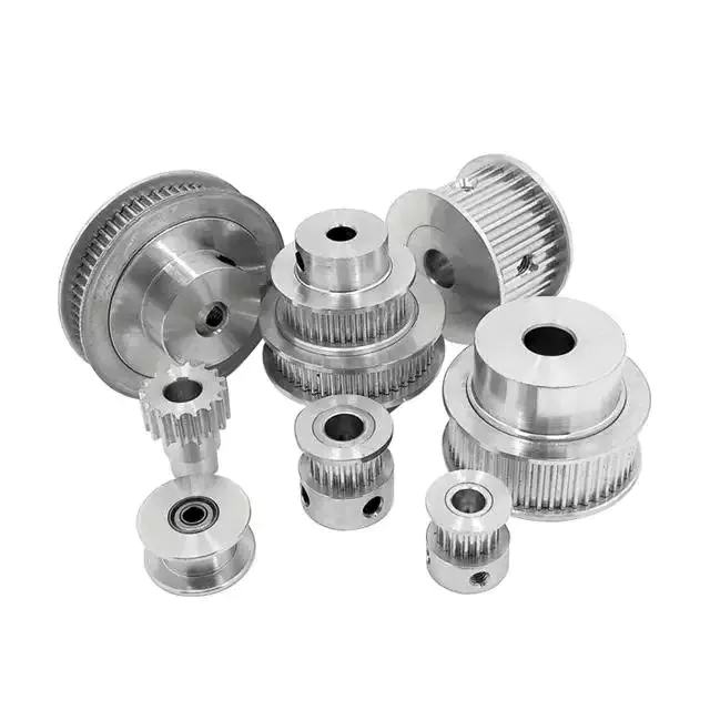
describe
The stress characteristics of a pulley depend on its size and construction. These stresses are derived by comparing the stress characteristics of different pulley designs. Stress criteria include static and fatigue strength analyses and specify maximum stress ranges. Stresses are calculated in a 3D stress field, including radial, tangential and axial stresses. The stress characteristics of pulleys are critical to the design and manufacture of industrial machines.
The principal stresses on the pulley shell are distributed in the tangential and hoop directions, close to the centerline of the pulley. If the pulley has a wide face, the axial stress occurring near the shell/disk junction can be large. The stress distribution was determined using British Standard BS5400 Part 10: Stresses at the shell and end disc connections for infinite fatigue life.
Another type of composite is a pulley with a belt section. Such structures are well known in the art. The corresponding help chapters for these elements contain detailed descriptions of the internal structure of these components. Chamfers between pulleys can also be defined using multiple tapers, with a smaller taper extending from midpoint 44 to large diameter 42. Additionally, the pulley can have multiple taper angles, and as the pulley moves away, the taper angle is from the center.
type
A pulley system uses a rope to move the object and 1 side of the rope to lift the load. The load is attached to 1 end of the pulley, while the other end can move freely in space. The force applied to the free end of the rope pulls the load up or down. Because of this, the mechanical advantage of the movable pulley is 2 to one. The greater the force applied to the free end of the rope, the greater the amount of movement achieved.
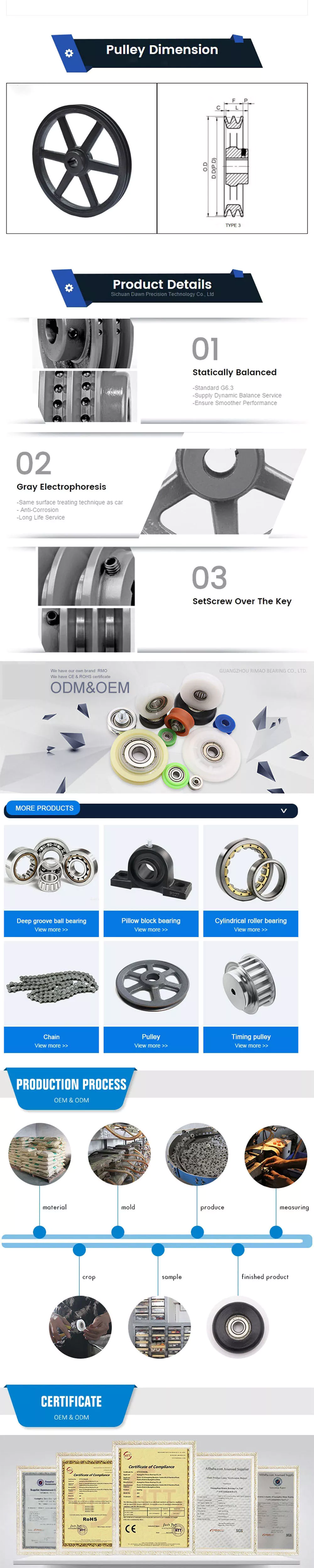
There are 3 common types of pulleys. The cast-iron variety has a rim at the front and a hub at the back. The arms of the pulley can be straight or curved. When the arms contract and yield instead of breaking, they are in tension. The top of the pulley centers the belt in motion and is available in widths ranging from 9mm to 300mm.
The rope, hub and axle are mounted on the pulley. They are common and versatile mechanical devices that make it easier to move or lift objects. Some pulleys change the direction of the force. Others change the magnitude. All types of pulleys can be used for a variety of different applications. Here are some examples. If you’re not sure which type to choose, you can find more resources online.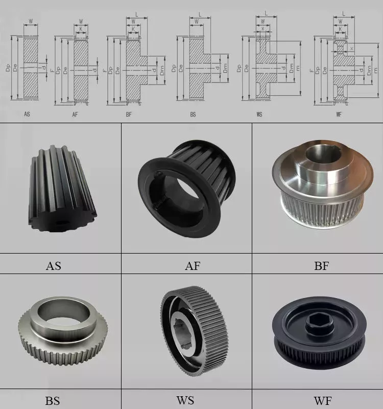
application
The applications for pulleys are almost limitless. This simple machine turns complex tasks into simple ones. They consist of a rope or chain wrapped around a wheel or axle. Using ropes, 1 can lift heavy objects without the enormous physical exertion of traditional lifting equipment. Some pulleys are equipped with rollers, which greatly magnifies the lifting force.
When used properly, the pulley system can change the direction of the applied force. It provides a mechanical advantage and allows the operator to remain separate from heavy objects. They are also inexpensive, easy to assemble, and require little lubrication after installation. Also, once installed, the pulley system requires little maintenance. They can even be used effortlessly. Despite having many moving parts, pulley systems do not require lubrication, making them a cost-effective alternative to mechanical lifts.
Pulleys are used in many applications including adjustable clotheslines in different machines, kitchen drawers and motor pulleys. Commercial users of pulley systems include cranes. These machines use a pulley system to lift and place heavy objects. They are also used by high-rise building washing companies. They can easily move a building without compromising its structural integrity. As a result, many industries rely on technology to make elevators easier.
Ideal mechanical advantage
The ideal mechanical advantage of a pulley system is the result of rope tension. The load is pulled to the center of the pulley, but the force is evenly distributed over the cable. Two pulleys will provide the mechanical advantage of 2 pulleys. The total energy used will remain the same. If multiple pulleys are used, friction between pulleys and pulleys reduces the return of energy.
Lever-based machines are simple devices that can work. These include levers, wheels and axles, screws, wedges and ramps. Their ability to work depends on their efficiency and mechanical superiority. The ideal mechanical advantage assumes perfect efficiency, while the actual mechanical advantage takes friction into account. The distance traveled by the load and the force applied are also factors in determining the ideal mechanical advantage of the pulley.
A simple pulley system has an MA of two. The weight attached to 1 end of the rope is called FA. Force FE and load FL are connected to the other end of the rope. The distance that the lifter pulls the rope must be twice or half the force required to lift the weight. The same goes for side-by-side pulley systems.
Materials used in manufacturing
While aluminum and plastic are the most common materials for making pulleys, there are other materials to choose from for your timing pulleys. Despite their different physical properties, they all offer similar benefits. Aluminum is dense and corrosion-resistant, and plastic is lightweight and durable. Stainless steel is resistant to stains and rust, but is expensive to maintain. For this reason, aluminum is a popular choice for heavy duty pulleys.
Metal can also be used to make pulleys. Aluminum pulleys are lightweight and strong, while other materials are not as durable. CZPT produces aluminium pulleys, but can also produce other materials or special finishes. The list below is just representative of some common materials and finishes. Many different materials are used, so you should discuss the best options for your application with your engineer.
Metals such as steel and aluminum are commonly used to make pulleys. These materials are relatively light and have a low coefficient of friction. Steel pulleys are also more durable than aluminum pulleys. For heavier applications, steel and aluminum are preferred, but consider weight limitations when selecting materials. For example, metal pulleys can be used in electric motors to transmit belt motion.
cost
Replacing a tensioner in a car’s engine can cost anywhere from $90 to $300, depending on the make and model of the car. Cost can also be affected by the complexity of the pulley system and how many pulleys are required. Replacement costs may also increase depending on the severity of the damage. The cost of replacing pulleys also varies from car to car, as different manufacturers use different engines and drivetrains.
Induction motors have been an industrial workhorse for 130 years, but their cost is growing. As energy costs rise and the cost of ownership increases, these motors will only get more expensive. New technologies are now available to increase efficiency, reduce costs and improve safety standards.
The average job cost to replace an idler varies from $125 to $321, including labor. Parts and labor to replace a car pulley can range from $30 to $178. Labor and parts can cost an additional $10 to $40, depending on the make and model of the car. But the labor is worth the money because these pulleys are a critical part of a car’s engine.